

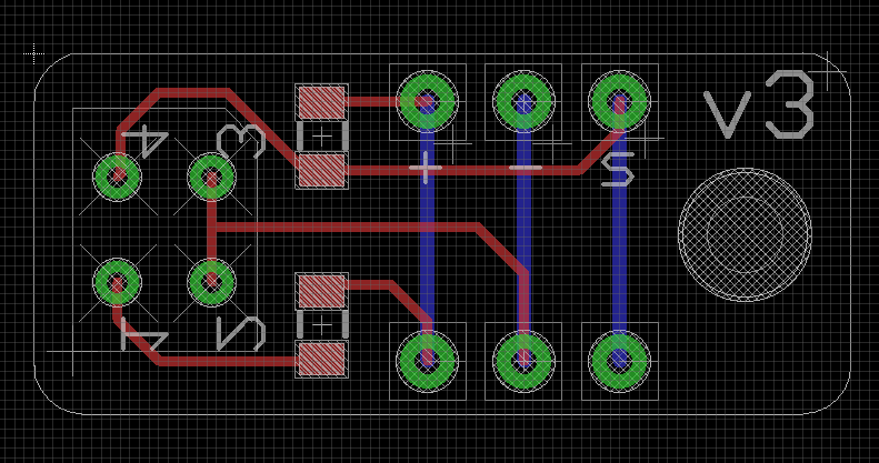
One of the projects I’m working on is a robot that has reflectance sensors around its circumference. I had trouble finding sensors that would work in the 0.25-0.75 inch range but eventually found the RPR-220. To mount this sensor, I made a breakout board with space for resisters and connections for positive, negative, and signal.
You can see the top and bottom of the breakout board in the image above. However, after working with it on my robot, I decided it would be better for the signal line to be closer to the hole so I made version 3. This means the image above won’t match the board design below – don’t worry. They work the same but just look a little different.
Now lets get to how to use this. The sensor is essentially two parts put together: an infrared LED and a phototransistor. The LED obviously emits an infrared light. The phototransistor is sensitive to infrared light and changes its resistance relative to the amount of infrared light received. So if it is close to a white surface, most of the infrared light emitted from the LED will be reflected and the resistance will be low. If it is far from the surface or the surface becomes less reflective (darker) the resistance will be higher. So this can be used to detect when your robot is at the edge of a dropoff or to look for lines.
The image below shows the pin numbers of the RPR-220. When you look at it from above, the pins are going away from you and you can see two circles on the top of the sensor. When you look at it from below, the pins are going toward you.

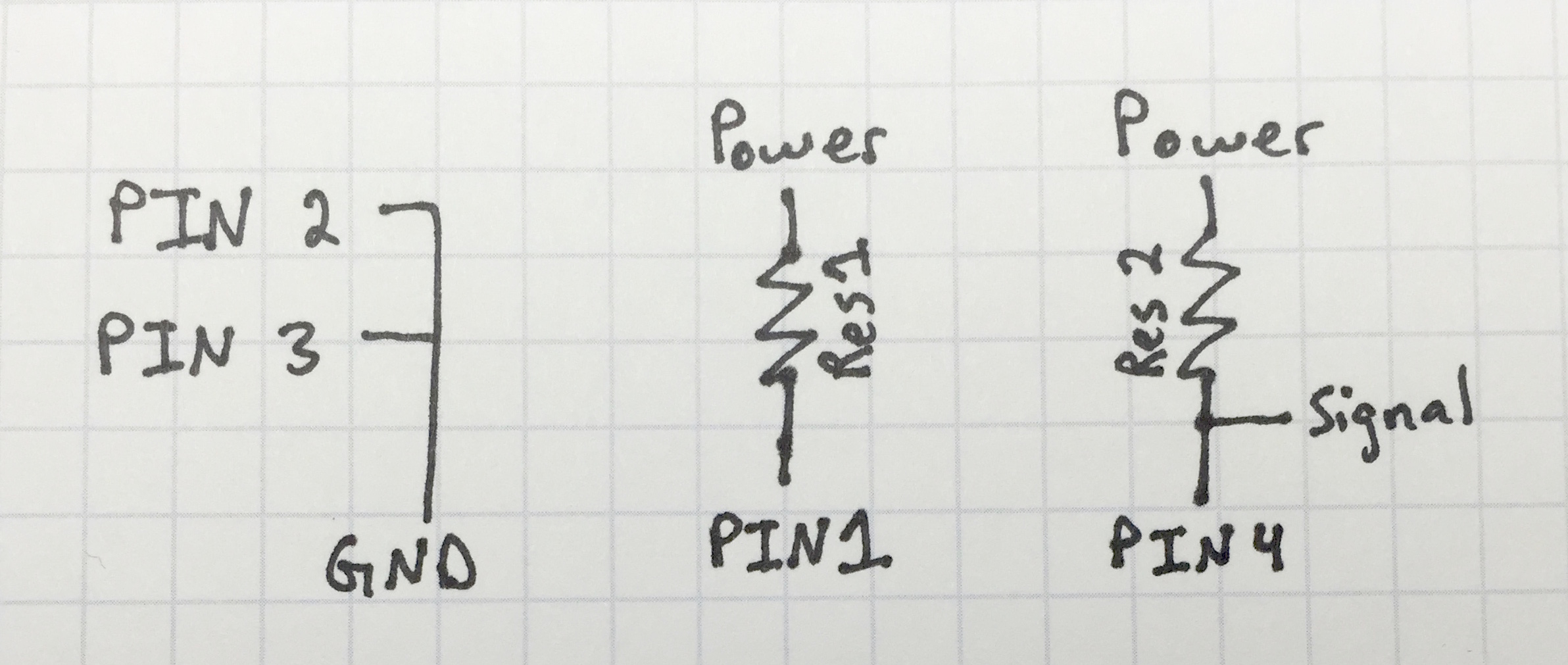
The above image shows the schematic for how we are going to connect the sensor using the same pin numbers as above. Pins 3 and 4 form the phototransistor, which is used as part of a voltage divider with RES2 to make a usable analog signal. Use a 10k ohm or similar resistor for this part. Pins 1 and 2 form the LED side so a resister (RES1) is used in series to limit the current. Determining which resister to use for this is a bit harder. The datasheet says that the led has a forward voltage of 1.34V (which is pretty typical for infrared LEDs) and a maximum current of 50mA (which is actually a pretty substantial compared to the 20mA red LEDs that I normally use). We can use Ohm’s Law rearranged into R = (Vs – Vf)/I to determine the minimum value for RES1, where Vs is the voltage at the source, Vf is the forward voltage of the LED (1.34V), and I is the maximum forward current of the LED. Plugging this in for both a 5V and 3.3V source, we get a minimum resistor value of:
R = (5-1.34)/0.050 = 73 ohms for a 5V source
R= (3.3-1.34)/0.050 = 39 ohms for 3.3V source
Remember, these are just the minimum resistor values. Ideally we should be a little more conservative. We also have to think of the power that will be dissipated through the resistor and make sure it isn’t more than the resistor’s maximum value. If we use the minimum resistor value of 73 ohms for a 5v source, the power is (P=IV) P=0.50*(5-1.34) = 0.183. Most surface mount resistors have a maximum of 1/8 (0.125) Watts so this would exceed that. (For the record, most through hole resistors have a max of 1/4 (0.25) Watts so they would be fine.) So for a 5V source, I would use a 150 ohm resistor and for a 3.3V source, I would use a 100 ohm resistor. Using the lower resistor on the 3.3V source helps make it a little brighter and it still only uses 20mA, which is far from the maximum.
This table gives the resistor to use and power dissipation for several common current values. Some are slightly off from the values I was going for (24mA vs. 25mA) but I did that to keep the resistor at a standard resistor value (150Ω vs. 146.4Ω).
5V – 40mA – 91Ω – 146mW
5V – 31mA – 120Ω – 112mW
5V – 24mA – 150Ω – 89mW
5V – 20mA – 180Ω – 73mW
5V – 10mA – 360Ω – 37mW
3.3V – 42mA – 47Ω – 82mW
3.3V – 32mA – 62Ω – 62mW
3.3V – 26mA – 75Ω – 51mW
3.3V – 20mA – 100Ω – 38mW
3.3V – 11mA – 180Ω – 21mW
Here is version 3 of the breakout board I made for the sensor. You can download it here. If you purchase this from OSHpark, it should cost about $1.60 for three, which isn’t bad at all. In fact, that’s less than the RPR-220 sensor. 🙂
If you have any questions or comments or concerns, put them in the the comments below!
