

Part of a robot controller I’m currently working on involves using some motor controllers. Since this robot controller is expensive and I’ve never worked with h-bridges (other than in professional products) I decided to make a breakout board to test it rather than risk making a stupid mistake on the robot controller. Luckily, it all worked perfectly so I’m sharing it with the world so that other people can learn from it.
EDIT: There is an update to this post here. I highly recommend you read it before continuing.
To start with, I’m using the TB6612FNG motor controller. It’s available from Digikey for about $1.75 in quantities of one. You can view the datasheet here but the key specs are:
2 channels
1.2 Amp average or 3.2 Amp max current per channel
Motor input voltages up to 15V
Logic levels of 3.3V and 5V
Sparkfun sells it on breakout board along with a couple of capacitors here and Adafruit sells one here. If you want to just use this chip and get up and running, buy one of these boards and make your life easier. But if you want to know how to incorporate this chip into your own work, this blog post should help. That said, my breakout board does have some advantages. Unlike the Sparkfun board, all of the low voltage inputs are on one side of the board while the high voltage inputs and outputs are on the opposite side. And unlike the Adafruit board, mine can be used in a breadboard without using screw terminals. Finally, mine has external flyback diodes on the board rather than needing to add your own. There is some disagreement about whether these diodes are necessary or not, but if I’m building an expensive controller, an extra 50 cents worth of parts are worth it to guarantee it won’t be a problem.
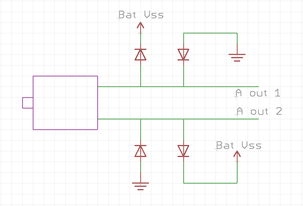
There hardest part here was learning which direction the diodes should be oriented. To help you, I’ve made a couple of schematics, which you can see below. If you are having trouble understanding the first because of all the lines, the second might be easier for you.

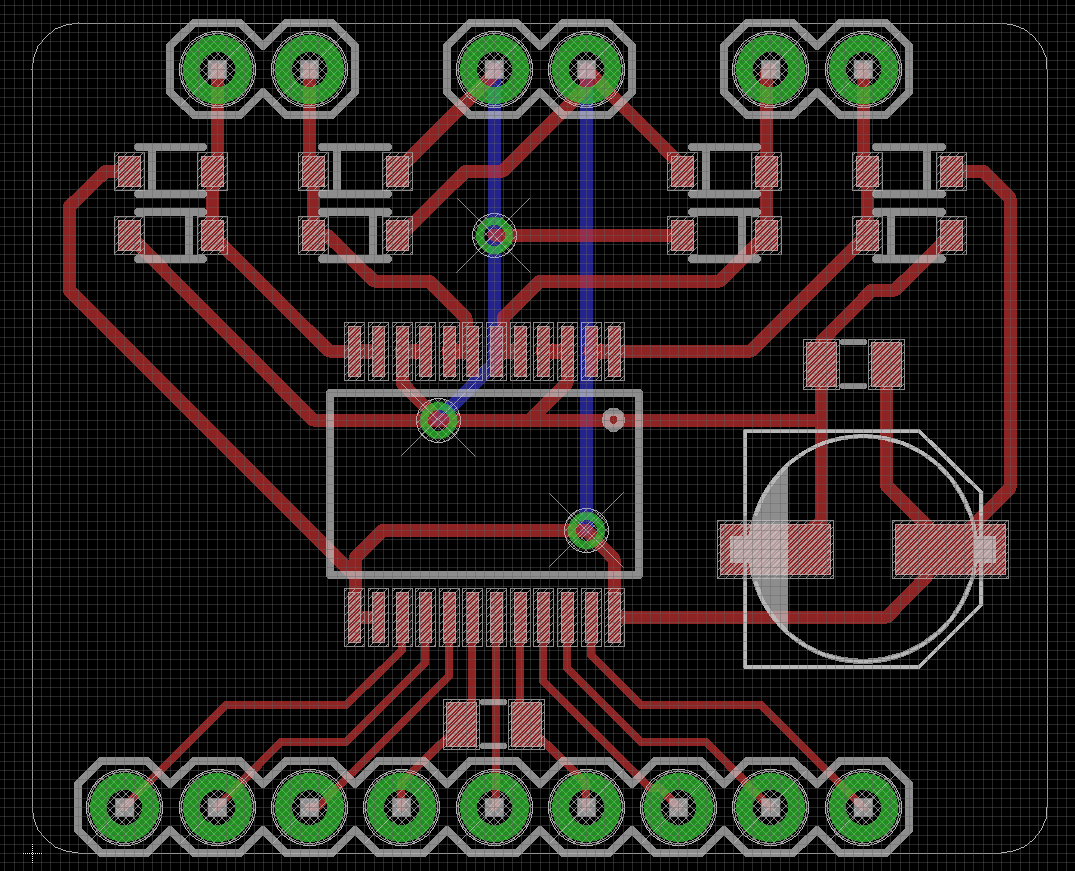
And here is the board design file. It is slightly altered from the version in the picture. One difference is that in this version the diode and capacitor pad sizes were increased to make them a little easier to solder. Another change is the size and layout. After I ordered it, I realized that it was 0.2″ too wide so that when you put it in the breadboard, you couldn’t attach wires on one of the sides. Of course this doesn’t matter when soldering directly, but it still annoyed me. Getting it to fit on a .9″ wide board was pretty difficult but once you lay out the diodes in the most efficient direction, it gets easier. Honestly, I was a bit surprised I got it to work with only three vias. I managed to keep the total area at about one square inch so a set of three from http://www.oshpark.com will set you about $5.
To test this, I wrote a simple Arduino program that reads in a number from serial (-255 to 255) and makes motor A go that speed (255 is full forward, -255 is full backward). Remember that standby needs to be pulled high to work. If Ain1 is high and Ain2 is low, it will spin clockwise and if Ain1 is low but Ain2 is high, it will spin counterclockwise at the speed determined by the A pwm pin. If Ain1 and Ain2 are both low, the motor will coast to a stop. If Ain1 and Ain2 are both high, it will stop immediately and will resist any rotation. This is called a short break and the two motor pins are shorted together so that it will resist rotation.
int Ain1 = 4;
int Ain2 = 5;
int Apwm = 6;

void setup()
{
  pinMode(Ain1, OUTPUT);
  pinMode(Ain2, OUTPUT);
  pinMode(Apwm, OUTPUT);

  Serial.begin(9600);
}

void loop()
{
  if(Serial.available())
  {
    int a = Serial.parseInt();

    if (a > 0)
    {
      // Spin clockwise
      digitalWrite(Ain1, HIGH);
      digitalWrite(Ain2, LOW);
      analogWrite(Apwm, (int)(a));
    }
    if (a < 0)
    {
      // Spin counterclockwise
      digitalWrite(Ain1, LOW);
      digitalWrite(Ain2, HIGH);
      analogWrite(Apwm, (int)(a*-1));
    }
    if (a == 0)
    {
      // Short Brake
      digitalWrite(Ain1, HIGH);
      digitalWrite(Ain2, HIGH);
      analogWrite(Apwm, a);
    }
  }
}
