

If you’ve read much of this blog, you’ll have noticed that something I like to do is test ideas on simple breakout boards before implementing them into larger projects. If something goes wrong, I haven’t wasted a bunch of time/money on it. And if something goes right, then I’ve got an example that I can keep around which will help next time I need to implement that particular part. This post shows my breakout of the NCP1402 boost converter that takes inputs from 1-4V and outputs 5V at up to 200mA.
This product is pretty straightforward so I’m not going to give a long introduction, but the idea is that you put in a small voltage on in the input and it outputs a larger voltage. It does this using a specialty chip, an inductor, two capacitors, and a diode. A gross oversimplification would be to say that it converts a small voltage and lots of current into a larger voltage and smaller current.
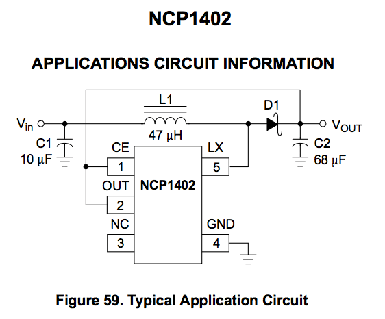
The exact part I used was NCP1402SN50T1G but there are versions that output many common voltages (1.9, 2.7, 3.0, 3.3, 4.0, and 5.0). At quantities of one, it costs about $0.80 which I think is pretty reasonable. You can find the datasheet here and honestly, it’s one of the better datasheets I’ve worked with and is worth a read. Below is the most common circuit that you would use with this part.
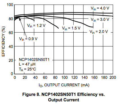
There are really two things to keep in mind when evaluating if this circuit is right for a particular application. The first is output current. The NCP14o2 is rated up to 200mA but that is only under certain specifications. The major limiting factor of the output current is the input voltage. As you can see in the image below, if you input 1.5V you can only get to about 60mA before the output voltage is reduced. However, most people will be using this with 3.7V LiPo batteries and you can see that even at 3V input there is no drop in output voltage at 5V output. The next thing to consider is the efficiency. We obviously want this conversion to be as efficient to save battery life and reduce heat. In general, efficiency decreases as the output current increases and as the input voltage decreases. With a 3.7V LiPo battery we would be looking at an efficiency of about 85 even at the max output current.

Below is a screenshot of the board design, which you can download here. The NCP1402 comes in a SOT23-5 package which is small enough to be easily placed but large enough that hand soldering is easy. In general, the traces should be as short and thick as possible to increase efficiency. My design has JST connectors on each end for input or output. There are also solder points for headers if you’d like to connect it to a breadboard. The version in the board file has been modified from the version in the picture above to make it slightly shorter and fit on the breadboard easier.

Links to the parts I used with mine are below. I make no guarentee that any of these parts are the best parts to use but it’s what I used and it works. The datasheet also has recommended part numbers near the end. The input capacitor should be a 10uF, ceramic or tantalum capacitor with a low ESR (.15-.3 ohm). For the output capacitor, a 68uF tantalum capacitor with low ESR is recommended but two parallel 22uF ceramic capacitors can be used to save space if necessary. The inductor recommended is 47uH, which is a good balance between current and voltage ripple. A higher inductor value will decrease current and voltage ripple but increase efficiency. A lower inductor value will increase current and voltage ripple but will decrease efficiency. An inductor with a DSR less than 1ohm should be used. Finally, the diode is the main source of loss in the circuit so pay special attention when choosing one. The datasheet recommends a schottky diode with small forward voltage (<0.3V), small reverse leakage current, fast switching speed / recovery time. Also make sure to choose one with current rated higher than anticipated inductor current and reverse voltage larger than output voltage.
68uF tantalum capacitor
10uF ceramic capacitor
47uH inductor
10V, 3A schottky diode
If you have any questions or think I’ve missed something, please let me know below!

One thought on “Simple Boost / Step-up DC-DC Converter Using the NCP1402”