

Last summer I started working with the rover team to modify the rover to be used for another research project. The original rover did extremely well at the competition but they were working under tight time restrictions and almost all of the work was done by undergrads. That meant there was a lot of work needed to fix and modify it.
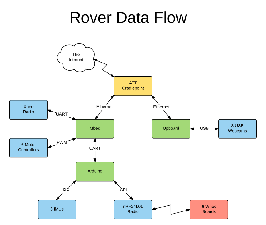
Here’s an image of what we started with. There is an ATT Cradlepoint, an ethernet switch, two Odroids, and two Mbeds, a power switch, and several voltage regulators. There’s also just over a metric ton of electrical tape – both traditional tape and liquid.
NO PICTURE HERE – SOMEBODY LOST IT – JUST IMAGINE 6 POUNDS OF WIRE IN A FIVE POUND BUCKET
Not only was this a mess and hard to work with, but we also needed to add an arduino, an xbee, and a nRF24L01 radio, which there wasn’t room for. We started by carefully analyzing our needs – which sounds obvious but the image above shows what happens when you don’t – and deciding on the best/minimum hardware to do this. Then, we ripped out everything that was there. We replaced both Odroids with an UPboard and and removed one of the mbeds because it was only used for the arm, which wasn’t necessary anymore. Because that was two fewer ethernet ports, we also got rid of the ethernet switch. So this defined the set of boards necessary: the Cradlepoint, UPboard, Mbed, Arduino, Xbee, and nRF24L01. Next, we drew up a set of connections, both data and power to fully understand everything that needed to be connected.

Once this was done, we decided to make some custom boards for the arduino/mbed/xbee/power. This would allow us to have strong connections – either soldered or using keyed connectors – rather than having to use header pins and lots of electrical tape. I chose JST XH connectors to use throughout the project. These connectors are keyed to protect against reverse insertion and provide a very strong connection that we don’t have to worry about falling out or vibrating loose. They are a 2.5mm spacing, which is very close to to standard 0.1″ headers; this means that should we need to use another connector, we can swap it pretty easily or use standard jumper wires. They are also readily available from a variety of sources and can be used with a cheap generic crimper. (Engineer PA-09 Micro Connector Crimpers)
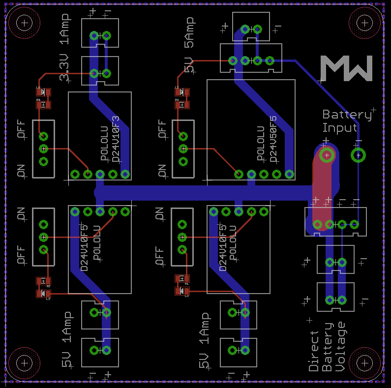
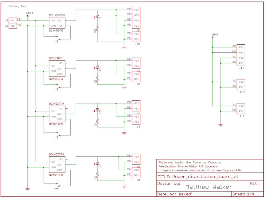
Power Distribution Board
The first board designed was the power distribution board. Now technically, we could have gotten away with a single 5V voltage regulator, but I knew that the design might change and other things would be added to the box. So instead I made a board that could have up to four separate voltage regulators installed – each with two plugs and an on/off switch – for the ultimate upgradability. The voltage regulators used were a standard model from Pololu that come in a wide variety of voltages. And if they really need some of that extra space in the future, you can cut two of the voltage regulators off and the board will function just fine. In the top right, the board has two big holes for 14 gauge wire coming from the battery. Then, there are three plugs connected directly to this battery power for the Cradlepoint and the fan. Note that the topmost of the plugs is actually a four pin connector where the left two pins are power and the right two pins are ground; this is so that you can increase the safe current draw for anything that needs more than the 3A current allowed by a single JST pin. The top right voltage regulator is a D24V50F5, which is a beefy model from Pololu that can handle 5A continuously. The other three are from the D24V10F line and are a bit smaller and can only provide 1A continuous. On each of them there is an on/off switch that connects the enable pin to ground to turn off the regulator as well as a power indicator led. The power trace that runs through the board is 120 mils wide and the ones connected directly to battery are a combined 270 mils wide, which will allow for plenty of current even if there wasn’t a fan always on to provide cooling. Finally, I just want to mention that all of the screw holes are symmetrical so that it can be mounted in any orientation.

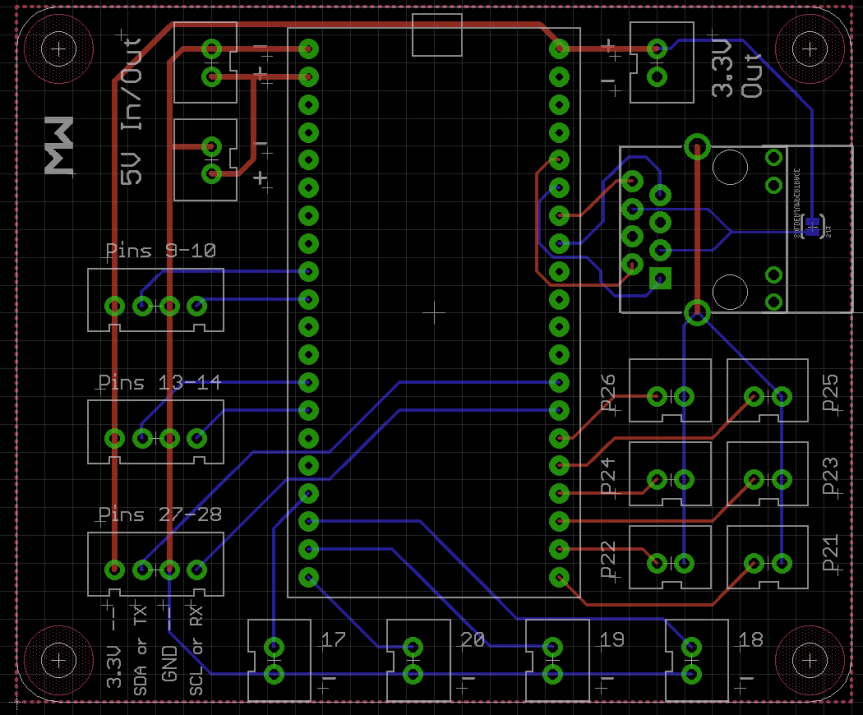
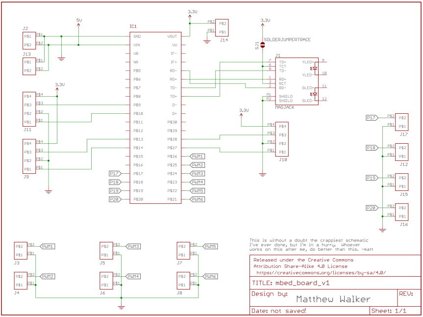
Mbed board
The next board was an Mbed board. The previous team had used a breakout for the Mbed (thankfully!) but they had not used any connectors and had soldered everything and coated it in liquid electrical tape. That’s not the design paradigm we want so the new board has the same JST connectors for all the used pins as well as some extras. In the upper left, there are two pins connected to the 5V input. Typically only one will be used but theres a chance something else will need to be daily chained to the same power supply and I had space so why not add it. On the opposite side there is a 3.3V out powered from the mbed onboard voltage regulator. Down the left side are three ports that each have power, ground, tx, and rx; and two of those three could also be I2C lines, if preferred. One of these serial ports will talk to the Arduino, one will talk to an xbee, and the other is free for the moment. Across the bottom are four ports where there is a pin and ground; one of the girls on the project talked about adding some indicator lights and I figured adding these ports where I had extra space would allow for maximum expandability. In the bottom right are six ports, each with a pwm pin and ground, to control the six wheel speeds. And finally above that is the ethernet port. Now, this is the first time I’ve ever used an ethernet port in one of my designs so I was super excited when it worked on the first try.

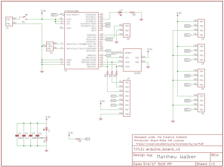
Arduino Board
And finally we have the Arduino board. Rather than use an Uno and tape in wires or even make a shield, I just decided to make a custom Arduino. I know a lot of people who would frown at the idea of using an arduino for something other than testing, but if I called it a custom board using an ATmega328P would they feel better? That’s essentially what it is and could be programmed without the Arduino IDE – in fact it doesn’t even have the Arduino bootloader or a method of programming over serial. So chill. It might be different if the chip wasn’t what we needed but for this, we needed I2C, UART, SPI, and a couple IO pins. Almost every micro in the world has that so it didn’t matter and since this rover will be used by lots of different groups in the coming years, the best way to make sure it will keep working is to make things as accessible as possible. In the top, the board has a shrouded 6 pin ICSP connector, which is the only way to program it. It also has a power led, an on/off switch, and a power connector. That big 8 pin connector at the bottom left goes to the nRF24L01 radio. Because there are dozens of libraries to work with that module, I looked through the most popular and broke out the 7, 8, and 2 pins since that was what was most often used. I put series resistors on the MISO, MOSI, and SCK pins in case the radio ever interferes with programming but right now they just have 0ohm resisters. On the bottom, there’s a status LED and two caps so the radio doesn’t brown out. Up the right side are four I2C connectors for the IMUs. We only needed two at the time but we had space so I added more and the team has since found needs for them. And the three pin connector is serial uart to the Mbed. Finally, there is an oscillator in the middle. The atmega has a built in 8MHz internal oscillator, which is probably fine for this application. But since it is technically only accurate to 10% and we are using fast uart, I put in the space for an oscillator to tighten things up. With the 3.3V supply it should technically only go up to 12MHz but I’ve seen lots of people operating out of spec at 16MHz just fine.


So there you go. None of this is terribly exciting but I needed to think through all of this for a documentation meeting so I figured I’d write it up on the off chance it helps somebody else. If you want any of the board files just let me know and I’ll add them. And if you have any thoughts/comments/questions put them in the comments below.

You actually make it appear really easy along with your presentation however I to find this topic to be actually something which I believe I might never understand. It seems too complex and extremely extensive for me. I’m having a look ahead on your next post, I will try to get the hold of it!