

My Master’s research involved sensing the environment using a UAV or “drone”. Do do this I needed some method of reading sensors, logging data, and transmitting it back to the ground station. This post shows the three different designs I used and talks about them a bit. I’m not expecting this to be a super popular post but just want to document it so I can get it out of my brain.
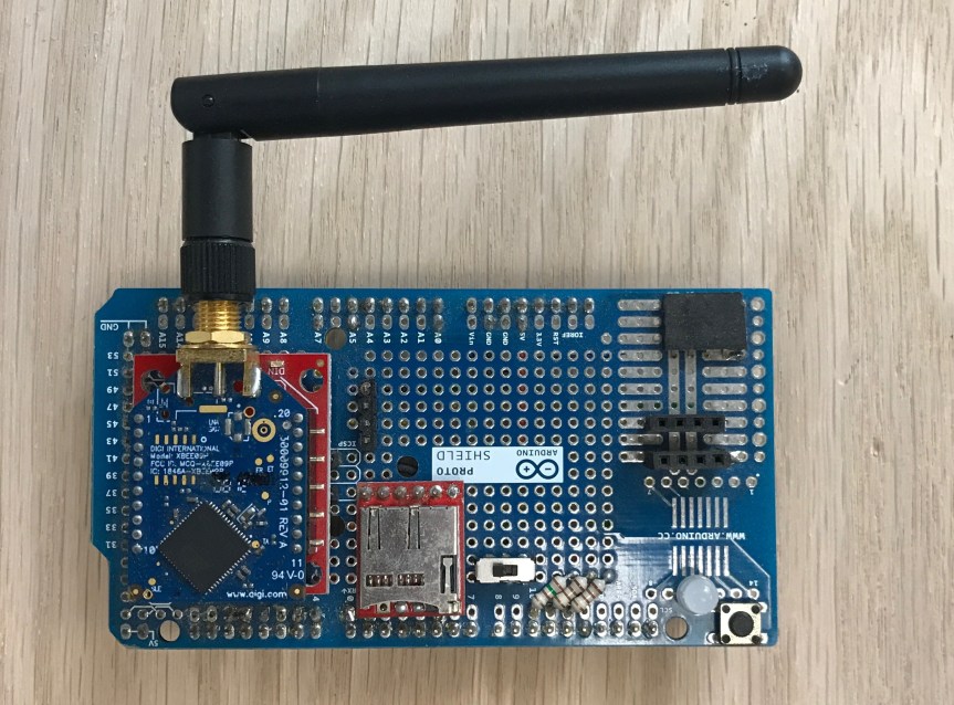
For a variety of reasons, I decided to start with an Arduino Mega and build my circuit on top using a protoshield. This design uses an Xbee 900MHz to transmit back to the ground station, a Sparkfun micro SD card logger, an RGB led, and a few header ports for sensors. Definitely pretty rough around the edges but it worked fine until we had a crash of the drone and several of the solder joints failed.
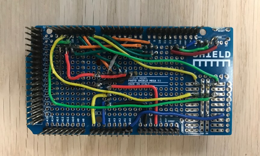
After the crash, I decided to learn EagleCAD and Make the shield correctly. Learning EagleCAD and SMD soldering was definitely a learning curve but I wouldn’t trade it for anything now. This uses the same 900MHz Xbee transmitter to transmit back to the ground station. The Xbee is on serial port 0 because I thought I needed all four serial ports but as it turns out, I only needed three and could have made my life much easier by not using serial 0 and only using it for programming. The other Xbee is also a standard 2.4GHz series one model; the matching one is connected to the serial out of the drone and this is how they communicate. The GPS is used only to get the current time and date from the GPS satellites to use for the datalogging. I went this route because I didn’t want to have to deal with real time clock getting out of sync but in hindsight, it would have been so much easier and saved a lot of time. The red board is a SHT15 breakout from Sparkfun to read temperature and humidity over I2C. In the bottom right is a micro SD card socket, which was a real PITA to solder when I first started. Several boards were ruined but I eventually got it. Along the top you’ll see several header ports for serial, i2c, and SPI. I didn’t know which I’d need so I just filled the space since the board size was determined by the shield. Likewise on the bottom there are four headers for analog pins – each header is analog, power, and ground. I didn’t end up need them for sensors so I used them to set preferences using a jumper. The biggest mistake here was not using keyed locking connectors. Not pictured on the back is a CR2032 coin cell battery and a logic level converter for the GPS and SD card. Note that I ran both Xbees at 5V power and logic and they worked fine. This was the design I used for almost all of my data and although we had problems, It’ll always have a special place in my heart.
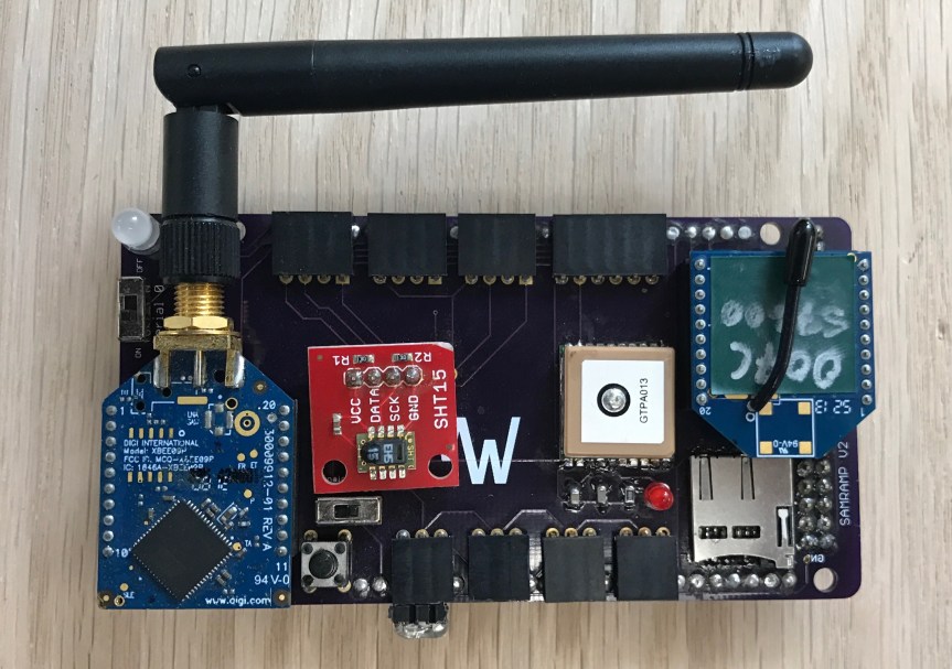
And this final version was designed at the end of my work as I looked to the next round of research. The first two versions of this board sat on a platform above the drone, which caused problems with weight distribution of both the board and the battery for it. With the third version, I wanted to integrate it into the central stack of the drone’s boards so it’s the same size as the Mikrokopter XL boards with the same hole spacing.
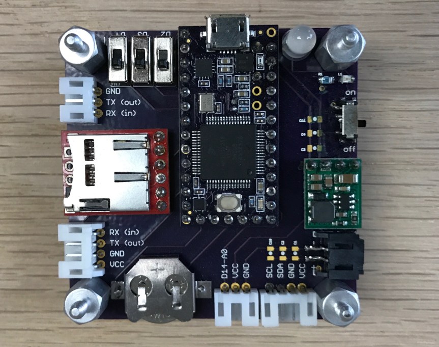
Instead of being a shield, this board kinda acts like a platform that the rest of the circuit is mounted to. The processing is done with a Teensy 3.2, which has a built in RTC using the crystal (not seen) and coin cell battery in the lower left of this picture. For datalogging I switched back to using the Sparkfun datalogger because it went down in price, was barely bigger than the sd socket, and removed some complexity from my code. Instead of powering this from batteries as in the last version, this time I tied into the batteries from the drone (14.8V nominal) and used a switching regulator to reduce the power down to 3.3V. I used a pair of diodes so that the teensy could be powered off of either the 5V USB for testing/programming or from the Mikrokopter batteries without me having to do anything. There are two serial ports, an i2c port, and an analog port. This time I used JST PH connectors, which are keyed and (kinda) locking. There’s also an on/off switch, an RGB led, and three individual switches to set preferences. This design is much better even though – or maybe because – it is much less complex.

Well there you go. As I said, I don’t think this will be too exciting for anybody but if you have any questions please fee free to ask them below
