

In another episode of clearing up old projects, here’s a controller I made for the rover that acts as an emergency override and also allows somebody nearby to drive it around. The rover is typically controlled over the internet but there are times you may want to be able to control it without the internet, including when the internet connection is down. Any signal from the controller also overrides the signal from the internet user so it can be used as an E-stop.
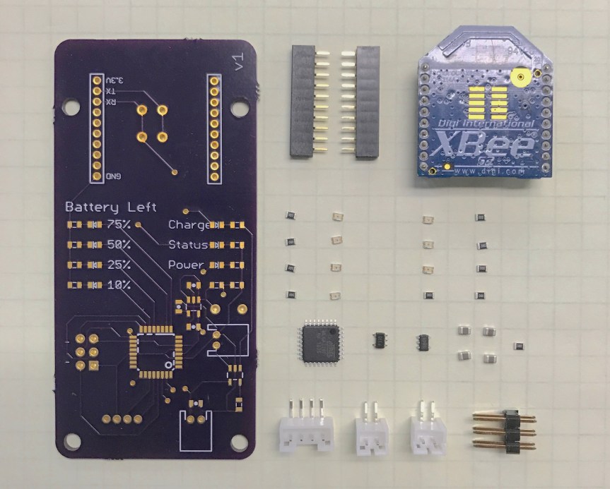
This controller is used to control the rover discussed here. It uses a wii nunchuck to get steering commands and then transmits them using an xbee. The design is a typical and boring arduino clone using the internal 8MHz oscillator and programmed using the ICSP. Somebody other than myself will be working with this in the future and this design was a compromise between quality and supportability.
Here’s the eagle file (sorry, no schematic for this one). Note that this is version 2 so it’s slightly different than pictures, but the only major change is that I shortened the length of the board so that it wouldn’t interfere with the mounting holes.

Power comes from a 1000mAh lipo under the board and a switch mounted in the back turns it on and off. The battery can be charged when the usb is plugged in using a lipo charging circuit. The nunchuck is hooked up using the I2C pins being very careful to keep everything at 3.3V. And finally, there are status LEDS for status, charging, power, and battery capacity remaining.
One frustrating thing was the voltage regulator. It’s a 3.3V LDO but can only provide maybe 50mA of current. I’d like one that could provide more but then the dropout voltage increases, which is important when you a working from a nominal 3.6V battery. It works fine in the current iteration but if I had more current I could put in a more powerful xbee and boost the range; instead we’ve found other methods that work pretty well. Perhaps I should have raised the voltage to 5V with a switching regulator and then dropped it to 3.3V. This would have been several more parts and more space required but I probably could have fit it. The battery can provide 1A continuous so I could probably get 850mA after all of the conversion and I’d only need 350mA for a more powerful xbee. Anyway, too late to worry about now but it’s something to consider. BTW, those holes/traces under the xbee are so that if I accidentally reversed the rx/tx lines, I can cut the trace and I have nice big holes to solder a wire to; it’s something I like to do when I have the space and the risk of having to order another board is high.
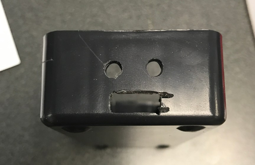
Also, I needed a method to charge the battery. I could have gone with a panel mount usb port but those are pretty bulky and I’d be worried about sand or water getting in. Finally, I figured why not cut the male portion off a USB and then you don’t even need another cord to use it; plus, it’s more resilient to dirt and water. I used a jst-ph plug just in case we needed to remove/replace the board at a later date.
I started by assembling the parts and then drilling holes for the cords and switch. After installing everything (with plenty of hot glue around the holes) I just had to screw on the plexiglass cover and it’s all set.

And there you go! Any questions or comments can be left in the comments section below.
