

This is the final post about the rover, I promise. In addition to the changes made to the electronics box, we also needed to get data from the wheels. Each wheel is a self contained unit with a battery, motor, and speed controller, which is sent pwm signals from the mbed. We needed to get the power draw from each wheel and this is the board I designed to do it.
The first thing to consider was how to get the data from the wheel to the electronics box. I suggested one of three things: 1) partially disassembling the rover and adding a couple more wires through the axel so that we could have communications lines; 2) converting the pwm line to a CAN bus line, and the board in the wheel could generate the pwm for the speed controller; and 3) something else. Those were vetoed and others decided to go with a wireless chip. I suggested using xbee’s because of their robust error checking, but again, the choice was made to go with cheap nRF24L01 radios. I know I sound bitter, but I’m mostly over it. 😉
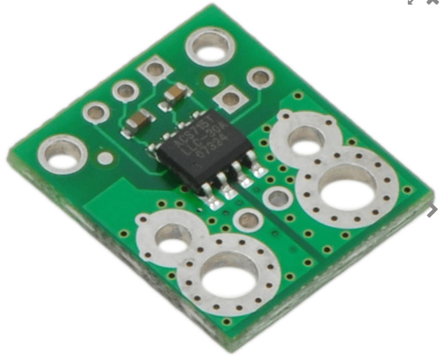
The next obstacle was reading the power draw. We decided to measure voltage using a simple voltage divider and current using an analog hall effect sensor from Pololu. Here is the sensor chosen. It can take up to 30A and outputs 144mV for each Amp measured.
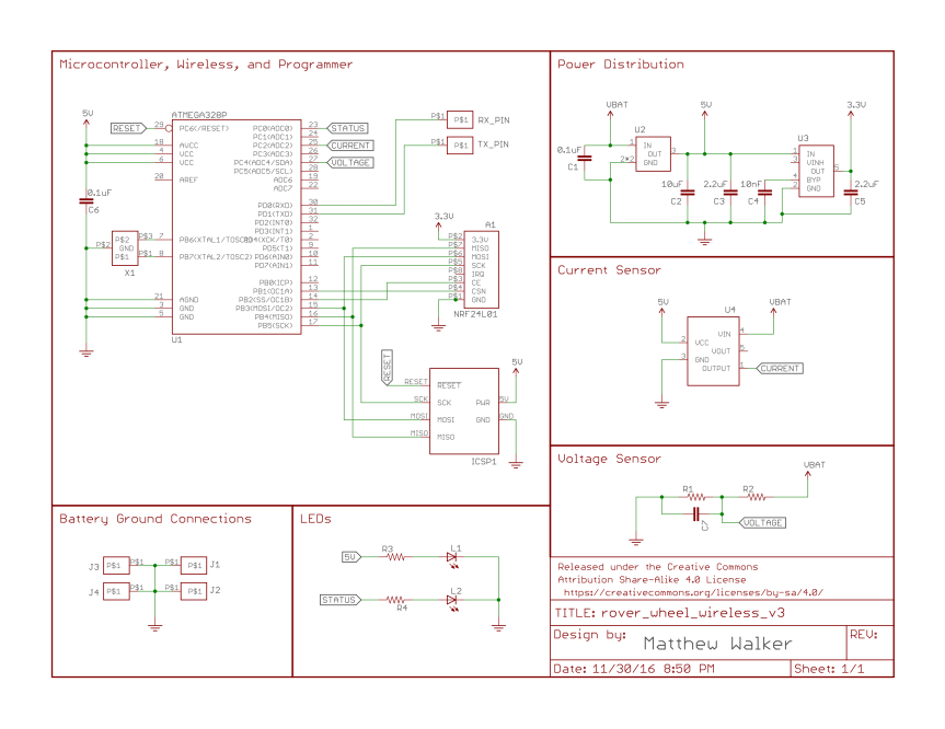
For the processor, I stuck with an ATmega328p programmed using the Arduino IDE and libraries because that’s what the other chips were and this would make it easier for others to maintain after I left. Programming is done with ICSP to reduce cost of footprint. There’s a cheap 16MHz oscillator, a status and power LED, and serial debugging spots. 13.2V power comes in from the sensor to a 5V regulator, which powers the arduino and the sensor. A 3.3V regulator after that provides power for the radio. These radios can tolerate 5V inputs but absolutely must have 3.3V power. The board is designed such that a battery connector is soldered onto each side of the current sensor – one of which plugs into the battery and the other into the speed controller. The positive line goes through the sensor to measure current while the grounds are connected. There is a 240mil trace for ground but that can’t handle 30A so there’s an extra hole to connect a jumper wire for the ground.
A couple notes: 1) Make sure to chose regulators carefully. This is a hot, enclosed environment so make sure the regulators aren’t close to saturation or they will burn up. 2) There is an unused spot for a capacitor in the voltage divider, which could provide filtering if necessary. 3) We’ve had a fair amount of trouble with the radio signal. It currently works but only in a very specific orientation which isn’t surprising given that it’s very close to a motor and the wheels are metal (gee, maybe a wired connection would have been better).
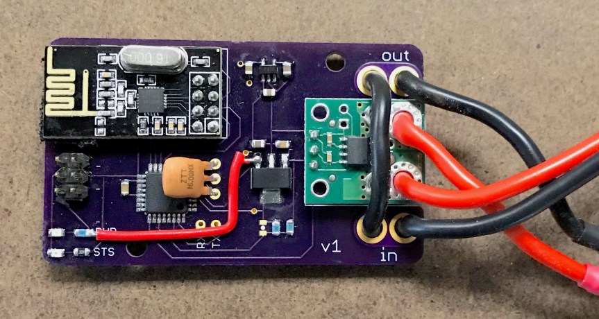
In version one, I made a few errors. 1) I forgot to connect the 5V line of the ICSP header and had to solder on an extra wire. 2) The status led is connected to (arduino) pin 13, which is the SCK line. Since the SCK line is used to communicate with the radio, the led can’t be used. These have been fixed in the schematic and board files below but are still messed up in the pictures of the board.

And there it is. Not super impressive or anything but just wanted to get it out there. If you have any questions or comments, please let me know in the comments below.
