
As I mentioned in a previous post, I’m starting to look at projects that for various reasons don’t require a full arduino. There are some projects that even the Arduino Pro Mini is too large for. For this, I’m looking at using an ATtiny85 since I only need a few pins. But first, we have to figure out how to program it. There are several ways to program a stand alone IC and future posts will show these, but this post will focus on how to program using an Arduino. There are already numerous tutorials of this online, but many of them are either incomplete or wrong. Others just don’t answer some of the questions I had when I started and this is what I hope to fix with my version.
The first step is setting up the arduino to act as a programmer. Plug your arduino into your computer like normal and select the appropriate serial port and board. In the arduino program, click File > Examples and select ArduinoISP. Upload to your board like any other program.
Next, we need to add the files to use the ATtiny board in the Arduino environment. The folks over at the High-Low Tech lab at MIT have created all the files needed to use the ATtiny84 and 85. Much of their instructions are replicated here along with my comments. These guys do great work and if any of them are ever in Norman, Oklahoma I’d be happy to buy you a drink or two as a token of my thanks.
Download the zip file from here. Unzip it and then move the unzipped file to the hardware folder that is in the Arduino sketchbook folder. If you don’t know where you Arduino sketchbook folder is, you can find it in the Arduino preferences. Unless you have added additional boards in the past, the hardware folder will probably not exist and you will have to create it. Restart the Arduino IDE and you should now see lots of new boards available to you.
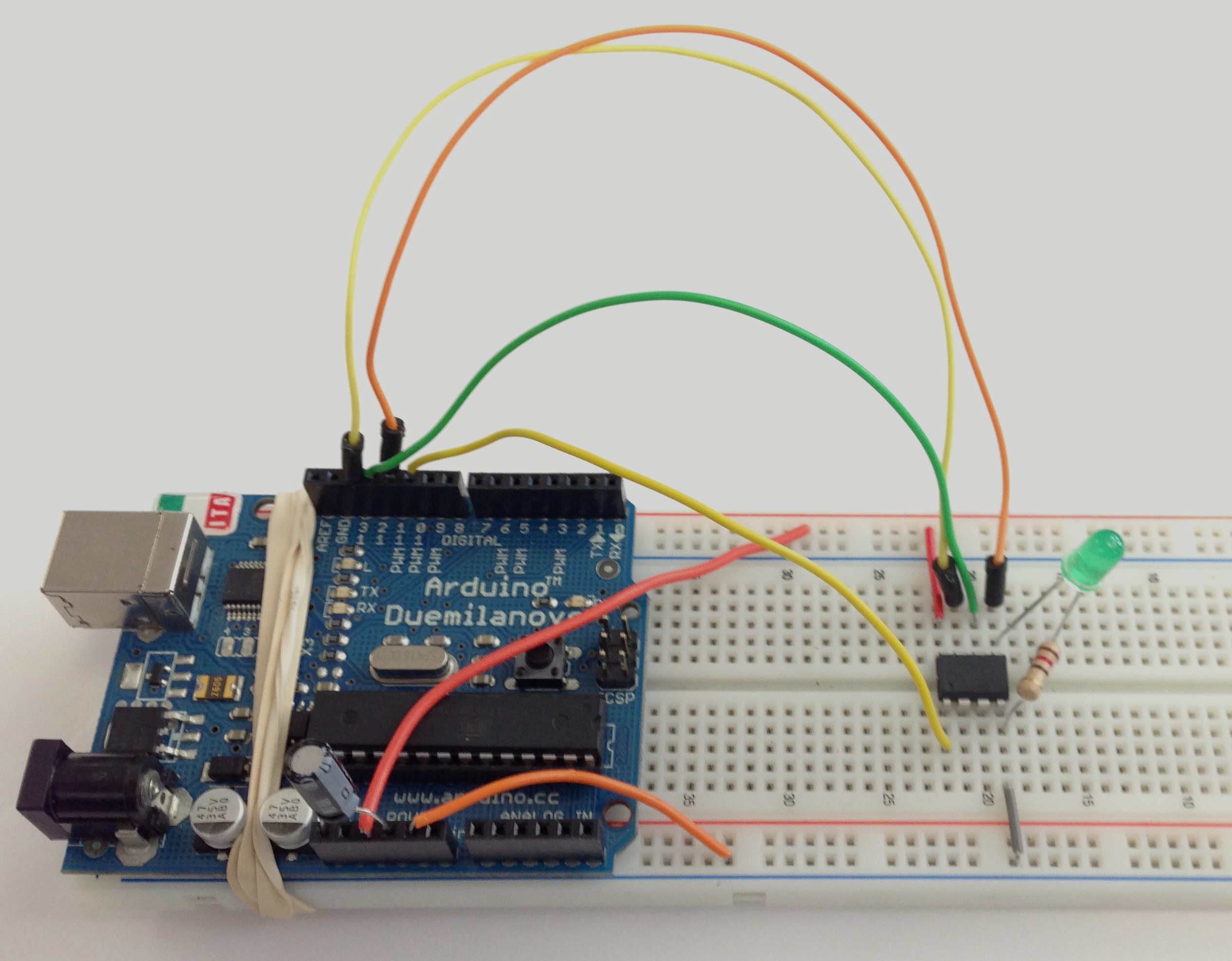
Now it’s time to wire the Arduino and ATtiny. Below is the pinout for the ATtiny85. Notice that the physical pin numbers do not correspond to the digital pin numbers. It’ll try to differentiate them to make it easier. Now we need to connect the ATtiny to positive voltage on physical pin 8 and ground on physical pin 4 plus connect the following:
ATtiny physical pin 7 to Arduino SCK – Uno pin 13, Mega pin 52
ATtiny physical pin 6 to Arduino MISO – Uno pin 12, Mega pin 50
ATtiny physical pin 5 to Arduino MOSI – Uno pin 11, Mega pin 51
ATtiny physical pin 1 to Arduino SS – Uno pin 10, Mega pin 53
And, since we need some way of detecting whether our sketch was uploaded correctly or not, lets attach a LED to physical pin 5 with a resister to connect it to ground. The resister value will change based on what voltage you’re running at. I’m using a 110 ohm resister and anything in that range should work.
The final thing we need to wire is a 10 microfarad capacitor between the ground and reset pins on the arduino. This prevents the arduino from resetting ensuring the the Arduino IDE talks to the Arduino ISP programmer and not the bootloader on the arduino. Some tutorials say you need this capacitor, others say you don’t. I tried it with an Arduino Uno R2, Duemilanove, and Mega R3. The Uno was the only one that worked without the capacitor. However, they all work with a capacitor, so I’d put one in just in case. The white stripe on the capacitor goes towards the ground pin.
Now, in the Arduino IDE, open the blinky sketch from the examples folder and change pin 13 to pin 0 in the sketch. Then change the board to ATtiny85 (1 MHz internal oscillator) and the programmer to ArduinoISP and hit upload. You should get the following error message which is ok to ignore. However, if you have a sync error or programmer communication error, you have a problem. If your LED is blinking, it’s time to move onto the next step. If it isn’t blinking but you didn’t get an error, try flipping the LED or making sure it isn’t dead.

Next, we want to change from the 1MHz internal clock to the 8MHz clock. To do this, change the board to the ATtiny85 (8MHz internal oscillator) and select burn bootloader. This will configure the internal fuse to switch to 8MHz. This is a semi permanent change. You’ll only need to do this when you want to change the speed, not every time you turn it on. Why would we want 8MHz? Well, you can do faster calculations but the big reason is that you need 8MHz to use the software serial package which we will discuss later. Note: no matter what you set the clock speed to, you can upload using either the 1MHz or 8MHz option. However, if you choose the incorrect one, things will go much faster (or slower) than you are expecting. (This with a blink sketch is a good way to test what speed you’ve set it at if you can’t remember.)
Another final note is that you can do all of this with the circuit hooked up including programming the arduino as the arduinoISP and programming the attiny. The led being hooked up will not affect things at all.

thanks for this! any ideas why it only works with a uno or deumilanove? I have tried for ages using an arduino pro mini as the ISP programmer (uses atmega328p – same as deumilanove) and it will not work.
It definitely does work using the Arduino Pro Mini as the ISP programmer, but it’s easy to make a mistake so there are some things you should double check. Firstly, you need to make sure you’ve programmed the Arduino Pro Mini with the arduino as isp sketch and make sure that when you uploaded it, you upload it to the correct board (arduino pro mini). Then you need to make sure you connect the pins correctly. For instance, if you want to program an uno with a pro mini, you would connect Pin 13 on the Pro to Pin 13 on the Uno; Pin 12 on the Pro to Pin 12 on the Mini; Pin 11 on the Pro to Pin 11 on the Uno; and Pin 10 on the Pro to the reset pin on the Uno. I tested it and it works with or without a capacitor on the Pro Mini. Finally, when you upload you need to make sure that you change the board back to the board you are actually programming (in this case the Uno) and that you choose to “Upload using Programmer”. If you have any more questions, just let me know.
Thanks for posting this. I look forward to using an ATtiny45/85 in a future project. I am a junior at OU studying Computer Engineering. Boomer.
SOONER!
They say a picture is worth a thousand words, and that photograph of the Arduino showed me exactly what I needed to know. i.e. where to put the 10 microF capacitor!