

I’m working on a robot project and one of the intended uses is to teach line following to college students. For this, I’m making an array of 9 RPR-220 reflectance sensors. This post will describe the part I’ve designed and the reasoning behind it. It’s a bit rambly so consider yourself forewarned.
There are many reflectance sensor arrays on the marketplace that are similar to what I am building. Here are links to some from Sparkfun and Pololu. The Sparkfun one is digital only with a potentiometer to adjust the trigger point. Pololu has both digital and analog versions available. Both of these use small surface mount reflective sensors like the one below. The reflective sensor is a combination of an IR led and a IR phototransistor. The output voltage of the phototransistor is relative to the amount of light reflected from the IR led. I discuss this more in the blog post here.

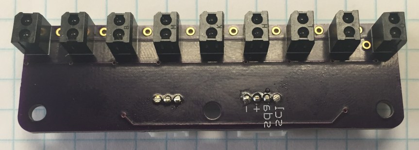
So the first question is: why use the RPR-220 rather than the QRE1113 like what Sparkfun and Pololu are using? Well, my use is a bit different than theirs. Theirs are made to be mounted at the front of a robot close to the ground (usually within half an inch). In my use, the array will be inside the robot. The bottom of my robot will be up to half an inch from the ground and the bottom plate is a 0.25in thick piece of plexiglass. Even though I am going to cut holes in the plexi for the sensors, with a surface mount sensor, it could be almost 0.75in from the ground. By using the RPR-220 which sticks out from the board about 0.26 inches, I’ll be within half an inch of the ground, which is just within the range of the sensor.
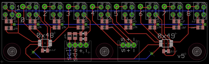
This brings me to the layout of the board, which is a bit unorthodox. To understand it you need to know a little more about the layout of the robot. Around the circumference of the robot will be seven reflectance sensors, including one in the front center of the robot, to detect lines and dropoffs. These sensors will be read using the analog ports of a microcontroller (probably a Teensy 3.2). At the front of the robot I want to add a sensor array to follow lines using PID; this array will replace the front middle sensor. And because I’m almost out of analog ports, this array will need to use and ADC (Analog to Digital Converter) that reads in four analog signals and transmits them over I2C. Up to four of these ADC chips can operate on the same bus.
Since I’m a little OCD, the middle sensor on the array is still read independently using an analog port on the microcontroller so that it matches the other reflectance sensors around the circumference of the robot. Because the ADC has four channels, this leaves the total number of sensors in the array at either 5, 9, 13, or 17. Nine sensors were chosen based on desired board size and resolution. These nine sensors are evenly spaced over the array. The middle sensor’s signal is broken out to a 3 pin JST connector (pwr, gnd, analog). The four leftmost sensors feed into one ADC while the four rightmost feed into another ADC, both of which are broken out to a 4 pin JST connector (pwr, gnd, scl, sda). There are also vias near the sensors at the top of the board to solder a wire so that the individual analog sensors can be read. The power and ground are kept separate for the middle sensor and the rest of the sensors so that I can turn off power to the outside 8 sensors when I don’t need them and want to save energy.
So that was a long bit of rambling to just let you know what’s going on in my mind about designing this sensor array. So let me show you what I’ve designed to accomplish most of the goals. Note that each ADC has a different address so that they don’t interfere. Also, the SDA and SCL pins have 10k pull up resistors as required by the ADC. The sensors are oriented vertically so that the IR led of one sensor is as far as possible from the neighboring phototransistor.
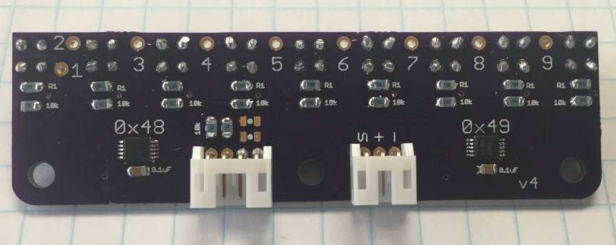
You can find a link to the eagle board file here. It is version two three four five and I’ve tested that it works using the Adafruit library found here. In earlier versions I put the sensors on the wrong side, redesigned it and put the sensors on the wrong side again, and then redesigned it to be smaller and cheaper but forgot a connection. The version pictured above is v4 but since then I added a forgotten connection and changed some of the labeling which is seen in the eagle file.
Below are links to the main parts with costs when buying in quantities of one from Digikey. The total cost to make a single one is about $42 but goes down very quickly if you make 3 or more. You could further reduce the cost by: 1) Getting the PCB produced at a cheaper house. The traces have tons of space so you don’t need amazing quality. 2) Use the ADS1015 chip which is only 12bit but will save about $7 per board. You can get the cost down to $25 if you make three and use the ADS1015 chip and I’d bet you could get the cost below $20 per board if you make ten and below $15 if you make a hundred.
RPR-220 ~ $1.49
ADS1115 ~ $6.51
ADS1015 ~ $2.83
3 Pin JST PH ~ $0.18
4 Pin JST PH ~ $0.22
Here is the code I used for reading the sensors. It is based on the Adafruit library listed above. I’ve modified it to have two chips by setting the address during declaration.
// Code modified from Adafruit_ADS1015 example file
#include <Wire.h>
#include <Adafruit_ADS1015.h>

// Initializing the chips and their addresses
// Use ADS1115 for 16-bit version
Adafruit_ADS1015 ads1(0x48); // Left chip
Adafruit_ADS1015 ads2(0x49); // Right chip

int sensorValues[10];  // Array to hold sensor values

void setup(void)
{
  pinMode(5, INPUT);  // This is for the middle analog sensor
  Serial.begin(9600);
  Serial.println("\nHello!");

  // Information to change gain removed for brevity
  // You can find it in original Adafruit example

  Wire.begin(); // This replaces ads.begin(), does the same thing
}

void loop(void)
{
  readSensorArray(sensorValues); // Call function to read sensors

  Serial.print("ADC 1: ");
  Serial.println(sensorValues[1]);
  Serial.print("ADC 2: ");
  Serial.println(sensorValues[2]);
  Serial.print("ADC 3: ");
  Serial.println(sensorValues[3]);
  Serial.print("ADC 4: ");
  Serial.println(sensorValues[4]);
  Serial.print("ADC 5: ");
  Serial.println(sensorValues[5]);
  Serial.print("ADC 6: ");
  Serial.println(sensorValues[6]);
  Serial.print("ADC 7: ");
  Serial.println(sensorValues[7]);
  Serial.print("ADC 8: ");
  Serial.println(sensorValues[8]);
  Serial.print("ADC 9: ");
  Serial.println(sensorValues[9]);
  Serial.println();

  delay(500);
}

void readSensorArray(int sensorValues[])
{
  // sensorValues[0] is not actually used.  It's only here
  //  so that the numbers match those printed on the array board
  // I know that's not correct procedure but bite me, it's easier
  // I've changed the printed numbers on the next one.
  sensorValues[1] = ads1.readADC_SingleEnded(3);
  sensorValues[2] = ads1.readADC_SingleEnded(2);
  sensorValues[3] = ads1.readADC_SingleEnded(1);
  sensorValues[4] = ads1.readADC_SingleEnded(0);
  sensorValues[5] = 2*analogRead(5); // Scale to match range of others (12 bit)
  sensorValues[6] = ads2.readADC_SingleEnded(3);
  sensorValues[7] = ads2.readADC_SingleEnded(2);
  sensorValues[8] = ads2.readADC_SingleEnded(1);
  sensorValues[9] = ads2.readADC_SingleEnded(0);
}
As I read back over this post, I realize that it isn’t very good. Probably one of my worst posts in terms of clearness and readability. But then again, this was a difficult problem figuring out how to lay out this board and if nothing else this post displays that. If you have thoughts about what you would have done differently or what you like about it, let me know in the comments below.
